We provide high quality and accurate electrical engineering services which are customized to meet individual project requirements. The key to our success is our ability to comply with the expectations and demand of our clients in an economical and timely manner.
We specialize in providing electrical drafting and detailing services for Residential Buildings, Commercial Buildings, Substations, Electrical rooms, Hospitals, Educational Buildings and Industrial Buildings, Monumental and amusement Centers.
We provide electrical drafting and electrical design services in Electrical Engineering that are cost effective, timely and responsive to client needs. We follow National Building Code of India 2005, NEC India and USA, ECBC 2007,BIS and IEC standards for designing Electrical Systems.
Our electrical design, drafting and detailing services include:
Design and Drafting of Lighting System
Design and Drafting of Power System
Design and Drafting of Power Distribution System
Design and Drafting of Fire Alarm System
We throughly work as per requirment of various codal provisions :
As per ECBC 2007 which is mandatory for commercial buildings or building complexes that have a connected load of 500 kW or greater or a contract demand of 600 kVA or greater. The code is also applicable to all buildings with a conditioned floor area of 1,000 m2 (10,000 ft2) or greater. The code is recommended for all other buildings.
The provisions of this code apply to:
Building envelopes, except for unconditioned storage spaces or warehouses,
Mechanical systems and equipment, including heating, ventilating, and air conditioning,
Service hot water heating,
Interior and exterior lighting, and
Electrical power and motors.
Lighting systems and equipment shall comply with the mandatory provisions of § 7.2 and the prescriptive criteria of § 7.3 and § 7.4. The lighting requirements in this section shall apply to:
Interior spaces of buildings,
Exterior building features, including facades, illuminated roofs, architectural features, entrances, exits, loading docks, and illuminated canopies, and,
Exterior building grounds lighting that is provided through the building's electrical service.
7.2 Mandatory Requirements
7.2.1 Lighting Control
7.2.1.1 Automatic Lighting Shutoff
Interior lighting systems in buildings larger than 500 Sq. m (5,000 ft²) shall be equipped with an automatic control device. Within these buildings, all office areas less than 30 Sq. m. (300 Sq.ft.) enclosed by walls or ceiling-height partitions, all meeting and conference rooms, all school classrooms, and all storage spaces shall be equipped with occupancy sensors. For other spaces, this automatic control device shall function on either
(a) A scheduled basis at specific programmed times. An independent program schedule
shall be provided for areas of no more than 2,500 Sq. m (25,000 ft²) and not more than
one floor; or,
(b) Occupancy sensors that shall turn the lighting off within 30 minutes of an occupant
leaving the space. Light fixtures controlled by occupancy sensors shall have a wall mounted, manual switch capable of turning off lights when the space is occupied.
Exception to § 7.2.1.1: Lighting systems designed for 24-hour use.
7.2.1.2 Space Control
Each space enclosed by ceiling-height partitions shall have at least one control device to
independently control the general lighting within the space. Each control device shall be
activated either manually by an occupant or automatically by sensing an occupant. Each
control device shall :
(a) Control a maximum of 250 Sq. m (2,500 Sq. ft) for a space less than or equal to 1,000 Sq. m. (10,000 Sq. ft), and a maximum of 1,000 Sq. m. (10,000 Sq. ft) for a space greater than 1,000 Sq. m. (10,000 Sq. Ft.)
(b) Be capable of overriding the shutoff control required in 7.2.1.1 for no more than
2 hours, and
(c) Be readily accessible and located so the occupant can see the control.
We provide the following designing services in Electrical: Electrical Designing for Building Services
Design of Lighting System
Lighting Load Estimations
Determining feeders for Lighting Panel
Light Fixture Layout Designing
Calculating the lux levels
Worst-case egress lighting estimation
Lighting distribution panel and emergency panel designing
Switchgear sizing
Determining the size of transformer for lighting distribution system.
Intelligent Lighting and proximity control
Dynamic façade lighting including LED lighting
Auditoria and Conference Hall Lighting and conferencing system
Public address and Digital Conferencing Systems
Interior lighting
Area classifications
Illumination levels
Anti-glare design
Types of fittings (surface, suspended, concealed)
Lamp type and colour
System data: mounting height, hours in use, reflectance
Estimated connected load and load per circuit
Connections to essential services with estimated loads
Exterior Lighting
Areas served and purpose
Type of fitting
Control and wiring method, including routes
Lightning protection
Need
Design criteria
Description of proposed design
Planning and Design 123
Communications
Justification for each type of area
Type of system
Areas served
Wiring method
Other features and safety considerations, like call systems, intercommunication systems, fire alarm systems and other special installations may be included as required in the design and computations for the total electric power requirements.
Design of Power Distribution System:
Calculating the total power requirements, power factor correction requirements, power load determination as per your standards
Determining the main transformer requirements, size of generator, HV equipments, metering and protective switchgear requirements, cable trays, trenches their optimum path, cable and wire sizing, one line diagram for distribution system
Switchgear sizing
Fault Level Determination/Calculation
Switchgear
Captive and Standby Power Supplies
Intelligent Substations and Distribution Systems 66/33/11 KV and 33/11KV/433V
Silent PLC controlled Diesel and Compressed Air Generating Sets 50 and 450 Hz
Pre-assembled Unified and Integrated Substation Systems
Intelligent UPS, Voltage Stabilizers, Inverters, CVT and Isolating Transformers
BMS, EMS, SCADA, DDC and other automatic control systems
Designing the life safety requirements
Determining earth protection requirements
Conventional Lightning Protection
Early Streamer type Lightning Protection
Surge Arrestor
ELCB, RCD and RCBOs
Chemical Earthing
Transformer ang Generator Earthing
Emergency Electrical Services
All hospitals should have a reliable alternative source of power, in addition to the normal electrical service, for emergency lighting, for operation of essential equipment, and for the safety of its occupants.
The alternative source should be from:
a generator, when the normal service is supplied from one or more central transmission lines, or
an emergency generating set or a central transmission line, when the
normal supply is generated on the premises.
The emergency generating set, including the prime mover, should be located
on the premises, away from the operating department and the ward block. It
should be reserved exclusively for supplying electricity in an emergency. The
recommended circuits to which power should be provided are:
For Lighting:
all exits, including exit signs, stairways and corridors
surgical, obstetrical and emergency room operating lights
nursery, laboratory, recovery room, intensive care unit, nursing station, labour room and pharmacy
generator set location, electrical switch-gear location and boiler room
one or two lifts, if needed for emergency
telephone operator's room
computer room, when available Equipment
nurses' call system
alarm system, including fire alarm
fire pump and pump for central suction system
blood bank refrigerator
sewerage or sump lift pump, if installed
equipment necessary for maintaining telephone service
equipment in operating, recovery, intensive care and delivery rooms
one electrical sterilizer, if installed
For Heating, Cooling and Ventilation System
Operating rooms,
Delivery,
Labour,
Recovery,
Intensive care unit ( ICU and ICCUs)
Nurseries and
Patient rooms
Catscans
MRI and X-Rays
Blood bank
Burns Ward
The capacity of the emergency generating set should be 50-60% of the
normal electrical load of the hospital, to maintain the minimum level of services.
The emergency electrical system should be so controlled that, after
interruption of the normal electric power supply, the generator brings full voltage
and frequency within 10 seconds to all the emergency lighting and equipment
listed above. Lights powered by storage batteries can be provided to augment the
emergency lighting during the period of transfer switching, immediately following
the interruption of normal service; however, these should not be used to substitute
for the generator set.
We provide the following Detailing and Drafting services in Electrical:
Lighting layouts depicting different Lighting fixtures, Emergency and Egress Lighting, Fire Escape Lighting. Occupancy Sensors etc.
Power Layouts depicting Receptacles, Microwave, Cabinet Heater, Refrigerator, Freezer, Ice Machine, Coffee Machine etc.
Power Equipments, Luminaries, Devices counts
Layouts, risers and details for telecommunication systems, audio video systems, security systems, PA systems and system integration.
Control Circuits, Terminations Diagrams, LV/HV electrical devices, Panel Schedule, Material List
Arrangements such as general substation site layouts, switchgear layout plan and arrangements, control room general arrangement, power transformer general arrangement, auxiliary transformer general arrangement and neutral earthing resistor general arrangements.
Single line diagrams such as single line diagram with relaying and metering, overall single line diagram, AC/DC supply single line diagram, substation distribution board single line diagram etc.
Electrical Schematic diagrams such as Cable Feeder Bay Schematic Diagram, Transformer Bay Schematic Diagram, Bus Sectionaliser Bay Schematic Diagram, Bus Coupler Bay Schematic Diagram, Auxiliary Transformer Bay Schematic Diagram, Shunt Capacitor Bay Schematic Diagram, AC/DC Distribution Schematic Diagram etc.
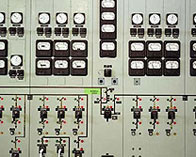
Control, metering and SCADA interface principle diagrams
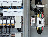
Control panel layouts such as PLC containing MCB, transformer, ELCB, contactor, relays, push buttons etc.
Cable/harness and Wiring diagrams
Create solar Array arrangements with the cable/wiring numbers and single line diagram after electrical system study of the existing sites.
Industrial and Substation Designing and Documentations
Arrangements
General Site Layout
Switchgear Layout Plan & Sections
Control Room General Arrangement
Power and Auxiliary Transformer General Arrangement
Neutral Earthing Resistor General arrangement
Single Line Diagram
Overall Single Line Diagram
Single Line Diagram with Relaying & Metering
AC Supply/DC Single Line Diagram
Sub Dist. Board Single Line Diagram
Cabling
Cable Routing Plan & Section-Basement
Control Room Cable Routing-Plan
Wall and Floor Openings in Control Building
Calculations
CT/VT Calculations
Grounding Calculations
220/110V Battery & Charger Calculations
AC Load (ST T/F) Calculation
MV / LV Cable Sizing Calculations
Indoor and Outdoor Lighting Calculations
Relay Setting Study
Grounding & Lightning Protection
Ground Grid Layout
Grounding Details
Lightning Protection Layout & Details- Substation Building
Cable Feeder Bay, Transformer Bay, Bus Sectionaliser Bay, Bus Coupler Bay, Auxiliary Transformer Bay, Shunt Capacitor Bay and AC/DC Distribution Schematic Diagram
Remote Ends Modification and Interfacing with Existing System
HV,MV,LV Power and Control Cable Schedule
Interconnection Diagrams ( For Each Panel, Cabinet & Equipment)
Control, metering and SCADA interface principle diagrams.
Technical Specification
Power Transformer
Circuit Breaker
Disconnectors
Surge Arrestors
Instrument Transformer
11 KV Switchgear
Power / Control Cables
Station Battery & Battery Charger
LVAC & DC Distribution Boards
Wave Traps
PLCC
R/C/I Boards & SCADA
DG Set
Auxiliary Transformer & DT
Erection Specification
U.P.S ( Uninterrupted Power Supply)
Street lighting
Automatic Metering
Capacitor Banks
Transmission Line Designing and Documentations
Basic Design of route length with help of surve map